Description:
Bruce Shapiro got me to design
and build the UBW (USB Bit
Whacker) project to solve his problem of disappearing parallel
ports on computers. The UBW design has exceeded all of my expectations.
As well as meeting the original design objectives, it has proven
itself a great platform for many forms of firmware. But there was
still a problem! Bruce traditionally used the UCN5804B stepper motor
driver chip for his EggBot
classes because it is easily breadboardable and very simple to
use. Unfortunately, they are now $17 each and very difficult to
find. Bruce wondered if I could design and build a replacement
driver that would still be mountable on a breadboard, would still
just need two input lines (step and direction) and would drive
bi-polar stepper motors. And so now we have the EasyDriver design.
There is now an official EggBot
that you can purchase! It uses an EiBotBoard, which I
designed and consists of a UBW + 2 BigEasyDrivers. The EiBotBoard is
now available for purchase at SparkFun
and Evil Mad
Scientists.
Knock-Off Easy Drivers
Over the years, the Easy Driver has become popular enough that
lots of people have copied it and are making and selling it. I am
flattered, truly I am. And this is open source hardware after all.
However, any other manufacturer of Easy Drivers besides SparkFun
and SeeedStudio are doing so without supporting me in any way,
which means I then have fewer resources to design new OSHW. The
license that the EasyDriver is released under requires at least
some attribution. These knock-off manufacturers will normally
strip off the "SchmalzHaus.com" silk screen before they build
'their' boards, see for example Electronics
DIY. It appears that Electronics DIY has decided to build
Easy Drivers, taking off the "Schmalz Haus" part of the silk
screen, and not mentioning anywhere on their page where the design
came from (i.e. no 'attribution'). This is in violation of the
license. There are lots of others too - all of the very
inexpensive EasyDrivers that are now on EBay, Amazon, and
Aliexpress are knock-offs. None of them support me in any way, but
I end up fielding tech support for their boards because people
write to me with questions. So please help support OSHW and buy
from SparkFun or SeeedStudio. They are fantastic and not only
believe in the value of OSHW but actively support designers like
me.
Quick Specs:
Each EasyDriver can drive up to about 750mA per phase of a bi-polar
stepper motor. It defaults to 8 step microstepping mode. (So if your
motor is 200 full steps per revolution, you would get 1600 steps/rev
using EasyDriver.) This setting can be easily overridden by tying
the MS1 and/or MS2 pin to ground to set the driver to use 1/8, 1/4
or 1/2 microstep mode (See the datasheet for the table of values).
It is a chopper microstepping driver based on the Allegro
A3967 driver chip. For the complete specs of the design, read
the A3967 datasheet. It has a variable max current from about
150mA/phase to 750mA/phase. It can take a maximum motor drive
voltage of around 30V, and includes on-board 5V regulation, so only
one supply is necessary. The best part - low cost. The parts cost is
easily less than $10, even less if you make the board yourself.
Quick Pin Description:
Please see the Allego A3967 data sheet linked above for complete
technical details. The Easy Driver is basically just a breakout
board for this driver chip, so the datasheet is your best source of
information about how it all works. However, if all you need is a
reference to the pins, here you go:
- GND : There are three GND (Ground) pins on the Easy Driver.
They are all connected together inside the board. Connect the
negative side of your power supply, as well as from any other
boards you are using to drive the Easy Driver to one or more of
the GND pins.
- M+ : This is the power input to the Easy Driver. Connect this
to the positive power supply lead. This should be a 6V to 30V,
2A (or more) power supply that is clean (low ripple).
- A and B : (four pins) These are the motor connections. See
below diagrams for how to hook these up. A and B are the two
coils of the motor, and can swap the two wires for a given coil
(it will just reverse the direction of the motor). Make CERTAIN
that this connection to the motor is solid, and NOT through a
connector that has any chance of intermittent contact (which
will fry the motor driver chip).
- STEP : This needs to be a 0V to 5V (or 0V to 3.3V if you've
set your Easy Driver that way) digital signal. Each rising edge
of this signal will cause one step (or microstep) to be taken.
- DIR (Direction) : This needs to be a 0V to 5V (or 0V to 3.3V
if you've set your Easy Driver up that way) digital signal. The
level if this signal (high/low) is sampled on each rising edge
of STEP to determine which direction to take the step (or
microstep).
That's it - those are the only signals that you absolutely need
to connect to anything. All the rest below are optional - in other
words, the Easy Driver sets them to reasonable default values.
- MS1/MS2 : These digital inputs control the microstepping mode.
Possible settings are (MS1/MS2) : full step (0,0), half step
(1,0), 1/4 step (0,1), and 1/8 step (1,1 : default).
- RST (reset) : This normally high input signal will reset the
internal translator and disable all output drivers when pulled
low.
- SLP (sleep) : This normally high input signal will minimize
power consumption by disabling internal circuitry and the output
drivers when pulled low.
- ENABLE : This normally low input signal will disable all
outputs when pulled high.
- PFD : This one is complicated - please see the datasheet for
more information. We default it to slow decay mode, but you can
over-ride with your own voltage on this pin. (or by populating
R17)
- 5V : This is an OUTPUT pin that will provide either 5V
(default) or 3.3V from the voltage regulator, at a small amount
of current (say 50mA - depends on input voltage) to power a
circuit that you may need powered. If you cut jumper APWR (SJ1)
then you can use the 5V pin as a VCC input to the Easy Driver,
powering it with your own VCC supply.
Oh, so awesome: where can I buy one!
I do not sell EasyDriver boards. This design is open source hardware
released under a creative commons license. It was developed in
conjunction with SparkFun, and they manufacture and sell it.
I'm providing Eagle schematic and board layouts as well as a Bill Of
Materials and instructions on how to build and use the design if you
want to take the design and modify it for your own use. If you do
decide to manufacture the EasyDriver for yourself or for sale,
please remember that royalties are the only way that I can continue
to provide support to Easy Driver users, so contact me.
SparkFun DOES sell EasyDriver
boards and they're only $15 each!
Also, please note that a Bigger, Badder, and all around Better
version of the Easy Driver has been designed. It's called the Big
Easy Driver (BED). You can read all about it at the Schmalz Haus Big Easy Driver
page.
News:
(08/18/2015) Added a new
section to the FAQ below about the two jumpers on the Easy Driver
and what they do. (Q15)
(11/16/2012) I did some measurements of temperature and current draw
with a SparkFun stepper motor and an EasyDriver. See the results
lower down this page, under Question 14.
(10/13/2012) Xavier wrote a great tutorial on using Easy
Drivers with Arduino.
(07/20/2012) MyDIYCNC is
now using Easy Drivers in some of their products, and is even
selling the driver boards in their store. Check out their cool CNC
machines.
(02/11/12) New Easy
Driver and Big Easy Driver Examples page - with Arduino code,
diagrams, etc.
(02/11/12) On a whim, I tested to see what the lowest voltage is
that the Easy Driver could run on. It had no problem running down to
about 4V (this is with a factory fresh Easy Driver 4.4). And, it ran
really cool. Note that you'll need a very low coil resistance motor
to make this work very well unless you are using full or half steps.
(01/03/12) Very minor update to schematic and BOM for EasyDriver
v4.4 - C3 is now 47uF. (SparkFun has always build them with 47uF
caps, but I've updated the documents to reflect this. It was
previously listed as 100uF.)
(08/19/11) We now have an Eagle
part library with the EasyDriver v4.4 in it for anyone who
wants to plunk down EasyDrivers on their board.
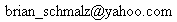
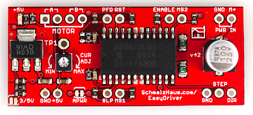
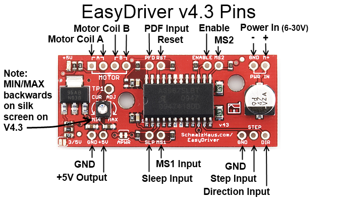
(08/03/11) It appears that there are two different types of current
adjustment pots being used for EasyDriver v4.4 production. If you
have one with the squarish white box of a pot (as per the v4.4
picture on the top of this page) then your MIN and MAX silkscreen
will be backwards. The previous version of the pot (see v4.3 pic)
has its pins in the right place, so that the MIN and MAX silk screen
labels are in the proper place. I don't know why the pot vendors
would choose to make their parts backwards, but that's how it goes.
Anyway, be careful. Note, the board is identical, it's only that one
pot is designed backwards from the other.
(10/21/09) Note that v4.3 and v4.2 (and possibly others) have the
MIN and MAX words backwards on the board. So if you have a small
motor, be CAREFUL! The likely result is that you will set it to MIN,
but a full 750mA will go through your motor, and it will get quite
hot. There will be a new v4.4 soon which will fix this problem.
(12/02/09) Version 4.3 has now been released to SparkFun - only
difference being two mounting holes.
(10/01/09) After a very long process (due to my procrastination and
schedule) we finally have a new
version of the EasyDriver! In very close collaboration with
SparkFun, I'm happy to release version 4.2 to the world. This new
version has several very nice new features, and still has the same
great price, $15! Thanks Spark for making this design available to
the world. (Some pictures on this page are from SparkFun.)
(09/17/08)Daniel Thompson has created an awesome
tutorial (with movie) on using the EasyDriver with an Arduino
to run stepper motors! Thanks Daniel!
NOTE: Many people attempt this setup without connecting the grounds
of the power supply, EasyDriver and Arduino (or other pulse source)
together. It tends to not work that way! So make sure you always
connect the grounds, and you'll have much better luck.
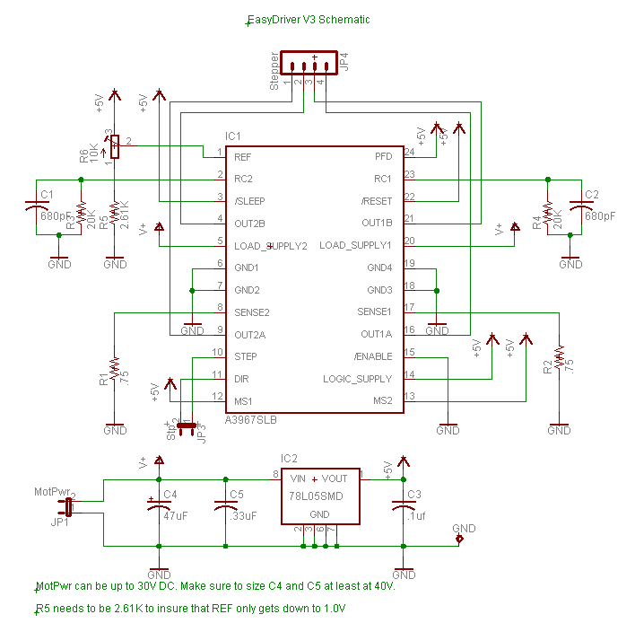
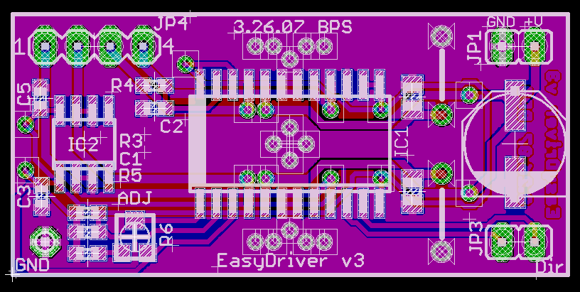
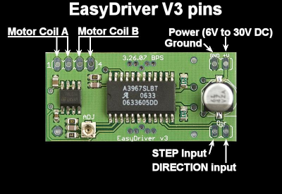
(5/23/07) Added project files for V3 design.
(4/6/07) Initial webpage created. Documents V1, V2, and V3
design revisions of EasyDriver board.
Easy Driver downloadable design files:
Version Notes:
- EasyDriver V1 - This was the first attempt. I had two boards
fabbed at BatchPCB (Very
highly
recommended). The design worked fine but because the board was
so small it got _way_ too hot. Also did not have variable
current limit or 5V regulator.
- EasyDriver V2 - This was the second attempt. I had some boards
fabbed at Futurlec
without solder mask or silkscreen. The board was twice the
size of V1, and routed to dissipate heat much better. The 5V
regulator was added. I have since modded the completed boards to
add the variable current limit.
- EasyDriver V3 - A refined version of V2, with the variable
current limit on the board, and switched to 0603 components. I
have not had any of these boards fabbed yet, as I'm confident in
the design from the V2 boards. - Update: SparkFun is now selling
these, and they work fine.
- EasyDriver V4.2 - Same footprint (as far as the holes go),
slightly longer board, with lots of new features. Here are the
difference from V3:
- Every I/O pin on the driver chip now comes out to headers,
and is pulled up (or pulled down) with 10K resistors. This
means you can now control every aspect of the driver chip
yourself. You can change MS1 and MS2 to do full step, half
step, quarter step or 1/8th step. You can put the chip to
sleep or in reset (drastically reducing power consumption).
Also, you get to play with PFD signal.
- That horrible tiny pot from V3 is now a somewhat larger pot.
:-) The really nice thing is that it doesn't have continuous
rotation, so you know where MIN and MAX current are
(finally!).
- A power-good LED has been added so you know when the
EasyDriver has 5V from the on-board regulator.
- A ground pin has been added next to the STEP and DIR pins.
This allows for a 3-pin cable to your Arduino or whatever you
use to drive the EasyDriver.
- By soldering SJ2 closed, you can switch the logic supply
voltage for the EasyDriver from 5V to 3.3V. This allows
interfacing with things like 3.3V Arduinos or other processors
that only output 3.3V.
- If you want to supply your own logic power to the
EasyDriver, cut jumper SJ1, and supply 3.3V or 5V into pin 1
of JP4.
- If you want the EasyDriver to power some small circuit, you
can use the 5V (or 3.3V) coming from pin 1 of JP4. How much
current can you pull from here? Well, feel the regulator. If
it is uncomfortably hot, then you're using too much. How hot
it gets depends upon what voltage you supply to the
EasyDriver.
- TP1 allows you to put a meter on the VREF signal as you turn
the current adjust pot. Measuring this voltage allows you to
calculate the actual max current being supplied to the motor.
See the schematic for information on how to do this math. I
never do this myself - I adjust the pot until things 'feel'
right on my motors since every situation is different.
- The value of the bulk cap is listed at 100uF on the
datasheet, but 47uF is all that is really necessary. The
bigger the better - but the Allegro datasheet says 47uF is
fine. SparkFun may use 47uF caps on their boards and that's
OK.
- EasyDriver V4.3 - Exactly the same as V4.2 except two mounting
holes have been added based on user requests.
- EasyDriver V4.4 - Exactly the same as V4.3 except the MIN/MAX
silk screen error has been fixed (well, not really, since the
current adjustment pot got changed) See note Q9 below.
- EasyDriver v4.5 - Major change from v4.4 was the addition of
series current limiting resistors on STEP and DIR as well as
pull downs on STEP and DIR. This helps prevent damage during
over voltage events.
Common Questions and Answers:
Q1) My motor says it can only take
2.1V at 2A. Will the EasyDriver (running from up to 30V) blow up my
motor or damage it in any way?
A1) Nope. You're safe.
Motors are specified with DC flowing through their coils. But what
we are concerned with is maximum current. The voltage spec of the
motor doesn't really matter, using the EasyDriver. (Or any chopper
driver, for that matter.) The EasyDriver will ramp up the voltage to
the coil until the _current_ reaches the maximum set with the pot
(max of 750mA). Then it will cut the power to the coil until the
current dips down again, then re-apply power, over and over again,
about 20,000 times per second. Any motor that's rated for 150mA/coil
(or more) will work with the Easy Driver just fine, no matter what
it's voltage rating. Note that if your motor is rated for less than
750mA/phase, you should adjust the current set pot on the EasyDriver
to dial down the maximum coil current to match your motor.
Q2) So
shouldn't I run the power to the EasyDriver at the voltage that my
motor is rated for? (i.e. 2.1V as per the above example)
A2) No. The voltage rating
of the motor DOES NOT MATTER. Really. Trust me on this. At least to
a point. You want to run the EasyDriver with as high a voltage as
needed for your application. Lower voltages produce a lot less heat
(on the ED and the motor) but produce lower maximum speed and
torque. Higher voltages (up to 30V) get you more torque at higher
speeds, but your ED will get much hotter. You make the decision.
Also, the higher the input voltage, the greater chance of frying
your ED if your motor wires come undone for some reason. Most people
are perfectly happy running their ED at 12V, and there are tons of
power supplies that work great at 12V and are cheap. The technical
reason for this is that the Easy Driver is acting like a switching
power supply. It is stepping down the voltage and stepping up the
current. The coil of the motor is basically like the inductor in a
buck converter. The chopper circuit switches the coil voltage on and
off to maintain a constant current through the coil.
Note that you can run the EasyDriver with a supply voltage of as low
as about 3V. This does NOT mean that you will get good stepper motor
performance at that voltage (actually, I can almost guarantee you
will not). However, even at 7V or 9V, the torque on most stepper
motors is near their max, at lower speed. Where you really need the
higher input voltage is at higher step speeds.
Another important point that a lot of people don't realize is that
many times, you don't really need the full, rated torque of the
motor for your application. For example, the small stepper motor
from SparkFun (https://www.sparkfun.com/products/9238),
develops a very large percentage of its fully rated torque even with
9V of input to the Easy Driver and the current adjustment turned all
the way down to 150mA/coil. In other words, you probably don't have
to break you back trying to make out the motor's rated current, and
thus rated torque. Try it in your system first - you may be
surprised with how much torque can be generated with a smaller
current and voltage.
Q3) How
much current does my power supply need to produce?
A3) The max that the
EasyDriver can shove into the motor is 750mA/coil. With 2 coils per
motor, that's 1.5A. So your power supply needs at least 1.5A to be
completely safe. However, you can normally get away with less than
that and still be just fine. Because of the way a chopper driver
works, the driver and motor actually form a sort of switching power
supply. Let's say that in order to reach 750mA/coil, the ED needs to
only ramp up the voltage to the coil to 6V. So if you're supplying
the ED with 12V, then the driver is working like a step down power
supply from 12V to 6V (we're sweeping a lot of things under the rug
here, but stick with me) so we only need to supply it with half of
the current it's sending to the motor (because the voltage is cut in
half, we only need to supply half the current going into the motor).
So in this case, you'd only need a power supply of 750mA. The best
advice here is to experiment. If your power supply is not 'strong'
enough, the voltage will dip and you will drop steps. (i.e. not
enough torque to keep the motor in the commanded position).
See the table under question 14 below for some experimental data I
took.
Q4) So why
does my bench power supply show 12V at 400mA when I know my motor
should be drawing 750mA/phase (1.5A total)? Huh smarty pants?
A4) See above answer.
Because of the way a chopper drive works is the real answer. You can
NOT trust any sort of power supply current measurement in order to
measure the actual coil current at any point in time. In actuality,
it is really hard to measure the actual current being delivered to
the coil, even if the motor is not moving. You need a special amp
meter attachment for a scope. The ones I've used at work are about
$5K each. (just for the stinkin' probe) So we just rent them when we
need them.
Also, see table under question 14 below for actual data supporting
this answer. The coil current is not equal the power supply current.
(Power supply current is always less than the sum of both coil
currents.)
Q5) How do
I adjust the current limit?
A5) Just turn R16 - the 10K
current limit pot. At one limit, it will tell the driver chip to
supply up to 750mA (limited by coil resistance and input voltage)
per coil. At the other limit, it is 150mA/coil. More recent
EasyDriver boards have silk screen words MIN and MAX, but you can
not trust them. This is because we can never be sure what pot
SparkFun uses to build the boards, and some pots are backwards from
the others. So always measure the voltage at TP1 and use that as
your guide for knowing which way is MAX (maximum TP1 voltage) and
MIN (minimum TP1 voltage).
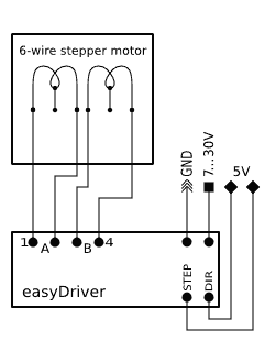
Q5.1)
What kind of stepper motors can I use EasyDriver with?
A5.1) The Allegro 3967
driver chip that the EasyDriver is based off of is a bi-polar
driver. This means it has a true H-bridge design internally, and
sends current both ways through each of the two coils. You can use
4-wire, 6-wire or 8-wire stepper motors. The only kind you can't use
is 5-wire stepper motors. (They need uni-polar drivers.)
Here's a little drawing on one way to hook up a six wire stepper
motor to the EasyDriver.
Q6) Why
does EasyDriver get so hot?
A6) PWM current limiting
drivers (so-called 'chopper' drivers) are turning the coil currents
on and off very rapidly. This makes sure that the maximum amount of
current (as set by R16, the current set pot) is _always_ flowing
through the coils of the stepper motor, even if it is not moving at
all. That's just how these things work. It means that the driver is
constantly passing that much current through, and because its
internal resistance is not zero, it dissipates some heat. If you
turn R16 all the way up so that 750mA flows through each coil, the
entire EasyDriver board will get hot to the touch. I've never burned
my finger on it, but it certainly gets hot. (At the minimum - about
150mA/coil - it only gets barely warm.) You can put a small fan
blowing across the board if you want to. But fear not, the driver
chip has a thermal cut out at 165 degrees C, so it will protect
itself. The boards have quite a bit of copper pour on them, to
maximize heat dissipation, which helps a lot. Also the voltage
regulator gets quite hot - this is because the driver chip needs
70mA at 5V for its logic supply. Depending upon what voltage you use
into the M+ pin, the voltage regulator needs to drop that down to 5V
(and throw the rest away as heat). So the higher the M+ voltage, the
hotter that regulator will get.
For actual quantitative data, see question 14 below.
Q7) What
hardware/software can I use to test my EasyDriver?
A7) Here's what I do. I
solder headers in the pins of the EasyDriver and put it into a
breadboard. I solder the wires on my stepper motor to a 4-pin .100"
male header, and plug that into the breadboard so it connects
properly to the EasyDriver. Then I take a PC power supply, and use
the 12V from that into the GND and M+ pins on the EasyDriver. Then I
tie the DIR pin to Ground with a wire. Then I take a square wave
with a frequency of about 500Hz and put it into the STEP pin. This I
generate with a signal generator or an Arduino or UBW. The motor
should be spinning at this point. You can then take the DIR pin and
connect it to +5V to see the motor go in the other direction. As the
motor is running, you can slowly adjust the current adjust pot to
see the effect that it has on the smoothness of the motor's motion.
Q8) How do
I connect my EasyDriver up?
A8) (For Version 4.2 and above) All
of the pins on the EasyDriver are on a .100" grid. If you solder
.100 headers into the pins you want to use, it plugs into a standard
breadboard. Once you plug it into a breadboard, you can then plug in
your stepper motor to the four motor pins (JP3), your 8V to 30V
motor power to the GND and M+ PWR IN pins (JP1), and your Step and
Direction signals to the STEP, DIR and GND pins (JP2). The GND pin
in the lower left corner of the board is really only there for
mechanical support, but it is tied to ground and you can use it as
such if you want. You could also construct a simple 'carrier' board
(on a proto board or some such) with female .100" headers for all
for the EasyDriver pins. Then it would be easy to wire up as many
EasyDrivers as you wanted to drive lots of stepper motors.
A8) (For Version 3) All nine of the
pins on the EasyDriver are on a .100" grid. This means it plugs into
a standard breadboard. Once you plug it into a breadboard, you can
then plug in your stepper motor to the four motor pins (JP4), your
5V to 30V motor power to the GND and V+ pins (JP1), and your Step
and Direction signals to the STP and DIR pins (J3). The GND pin in
the lower left corner of the board is really only there for
mechanical support, but it is tied to ground and you can use it as
such.You could also construct a simple 'carrier' board (on a proto
board or some such) with female .100" headers for all for the
EasyDriver pins. Then it would be easy to wire up as many
EasyDrivers as you wanted to drive lots of stepper motors.
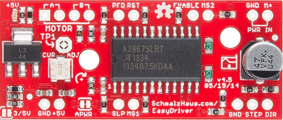
Q9) My
Easy Driver's labels don't match what I see in the picture. Why not?
And how do I know which way to turn the current adjustment pot?
A9) There are some mistakes
with the EasyDriver silk screen on previous board revs. On some of
the earlier versions the STEP pin is not labeled, and the motor coil
output pins are not clearly marked. This diagram should help clear
up any problems:

One important thing to note is
that, on various versions, I've gotten the silk screen for the
MIN/MAX of the current adjustment pot backwards and SparkFun has
used various potentiometers that have reversed directions (thus
making the 'correct' silk screen backwards again). SO! You never
really can trust the silk screen on the Easy Driver. Instead,
what you need to do is put a volt meter on the TP1 test point
(which is connected to the VRef pin on the driver chip) and
measure its voltage with respect to ground. The largest voltage
on that test point (normally 5V) will result in the largest
current through the motor coils (750mA), and the smallest
voltage on TP1 (1V) corresponds to the least current through the
motor coils (150mA).
Q10) Man,
this is a lot of work to just use the A3967 chip. Can't I just
solder down a bunch of A3967s on my own board design and save a ton
of money?
A10) Sure. <grin> The
EasyDriver board is for people who want to spend a little bit of
money and not have to worry about making their own board to hold the
driver chip. It is for people who want a design that will 'just
work' instead of having to try stuff out for themselves. It is for
'software folk' (like myself) who want to spend time writing code,
not debugging hardware. It is for people who want to build an EggBot
but can't get the 5804B chips. If you're designing your own board,
then don't use an EasyDriver! Just put the chip down on your own
board yourself.
Q11) The
datasheet for the driver chip shows that the motor connects to pins
OUT1A, OUT1B, OUT2A and OUT2B, and the diagram in the datasheet has
one coil connected across OUT1A and OUT1B, and the other across
OUT2A and OUT2B. But the Easy Driver only has A, A, B, B for
motor connections, and it looks like one coil should be connected
across the two A pins and the other across the two B pins. What's up
with that?
A11) Yeah. Ooops.
Clearly that was a pretty bad choice for the Easy Driver labels. On
a bi-polar stepper motor, there are four wires that connect to two
coils. Each coils has two wires. The Easy Driver calls those two
coils A and B. So one coils' wires are to be connected across the
two A pins, and the other coils' wires are to be connected across
the B pins. The driver chip datasheet refers to these two coils as
coil 1 and coil 2. Sorry for the confusion. See the diagram above
for the accurate connection diagram for the Easy Driver.
Q12) So
what's the deal with microsteps? How do I set what number of
microsteps are used?
A12) Microsteps are a way to
take a single, full step, and break it down into smaller steps. The
A3967 driver chip carefully controls the current to each coil to
cause the rotate to move to positions in between the normal full
step positions. This allows for smoother motion, reduced mid-band
resonance, and higher positional accuracy and resolution at the
expense of a more complicated driver and somewhat reduced torque.
The Easy Driver is able to operate in 1/8th, 1/4, half, and full
step (2 phase) modes. These four modes are selected by the logic
levels on the MS1 and MS2 input pins. Normally, the pull-up
resistors on the Easy Driver hold MS1 and MS2 high, which results in
a default setting of 1/8th microstep mode. You can pull either
or both to ground to select the other 3 modes if you want. See the
table below:
MS1
|
MS2
|
Resolution
|
low
|
low
|
Full Step
(2 phase)
|
high
|
low
|
Half step
|
low
|
high
|
Quarter
step
|
high
|
high
|
Eight
step
|
Q13) Help!
I think my Easy Driver is not working like it should. How can I know
if it's become damaged?
A13) One thing you can do
is to measure some of the resistances and voltages on the board to
see if it has become damaged.
- With everything
disconnected from the ED, measure the resistance from each
of the four motor output pins to GND and M+. All 8 of these
measurements should be over 1MOhm.
- Again
with everything disconnected, measure the resistance
between the four motor output pins themselves. And again,
all measurements should be over 1MOhm.
- Again
with everything disconnected, measure the resistance from
STEP and DIR to GND and +5V pins. Again, all of these
should read greater than 1MOhm.
- Now
connect just GND and M+. Do not connect anything else to
the ED. The LED should come on and stay on. Measure the
voltage at +5V to GND. It should be right around 5V.
- Now
measure the voltage at each of the four motor output pins
to GND. Two of them should read at about the same voltage
that is at M+ (your power supply voltage - mine is 12V),
and the other two should be almost zero - I measure
0.018V.
- Also check for any missing
components. SparkFun has been known to ship boards
with resistors or capacitors
missing. See the picture above - there is _supposed_
to be one part missing, but only one.
(It's the resistor to the right of the word MOTOR.)
If your board has any missing parts,
it might not work well.
If all of
those measurements pass, it doesn't mean you ED is not smoked,
but it does rule out internal shorts, which is the most common
failure mode for these driver chips.
Q14) But Brian, can't you give us some real
world numbers for power consumption and heat and stuff like that?
A14) Sure! Here you go. Here are some temperatures I
measured.
The test setup was as follows:
- Lab grade power supply powering a v4.4 Easy Driver.
- Current limit pot set to maximum current (750mA/coil) which
was called MIN on silk screen.
- Digilent chipKIT uC32 board running simple AccelStepper sample
program which ramped speed from 0 steps/second (for 2 seconds)
to 2500 steps/second (for 8 seconds) repeating.
- Ambient temp in my lab was 70F (21C).
- For each test I let the system run for about 30 minutes at
each input voltage to stabilize the temps.
- EasyDriver was mounted on a breadboard, and no cooling was
used.
- Temperatures were taken using a calibrated IR thermometer.
- The coil current was measured with a IProber 520 current probe
connected to a Rigol DS11102D scope.
Notes on testing: The coil current is not 750mA for some motors and
input voltages because the coil resistance limits the current, not
the chopping of the driver chip. With the ROB-09238 motor, you can
never reach full current because of the coil resistance. The driver
chip's internal thermal shutdown temp is 329F (165C). With some
combinations of motor and input voltage, the driver chip will go
into thermal cutoff because this internal temperature is achieved
inside the driver chip. I have marked these in the table with
red cell color. When the chip does this, it will cycle the output
drivers to the motor on and off (about 1 second on, 1 second off).
And yes, I exceeded the rated current for ROB-09238 (330mA) and
ROB-10551 (400mA). Normally, you would set the current adjustment
pot so that the EasyDriver delivers the max current that your
particular motor is rated for. But I wanted to show maximum currents
and heating with this table.
Motor = "Stepper
Motor with Cable", SparkFun ROB-09238 (coil
resistance = 32.6 ohms, 32oz-in torque)
|
Input Voltage
|
Power Supply Current
@ rest
|
Power Supply Current
@ 2500 steps/sec
|
Actual Coil Current
@ 2500 steps/sec
|
Motor Temp
|
Driver Chip Temp
|
9V
|
450 mA
|
120 mA
|
138 mA
|
86F (30C)
|
121F (49C)
|
12V
|
600 mA
|
190 mA
|
224 mA
|
113F (45C)
|
152F (67C)
|
24V
|
1.1 A
|
440 mA
|
475 mA
|
217F (103C)
|
213F (101C)
|
30V
|
1.0 A
|
540 mA
|
600 mA
|
225F (107C)
|
240F (116C)
|
Motor = "Stepper
Motor - 68 oz.in", SparkFun ROB-10846 (coil
resistance = 1.8 ohms, 68 oz-in torque)
|
Input Voltage
|
Power Supply Current
@ rest
|
Power Supply Current
@ 2500 steps/sec
|
Actual Coil Current
@ 2500 steps/sec
|
Motor Temp
|
Driver Chip Temp
|
9V
|
470 mA
|
510 mA
|
780 mA
|
83F (28C)
|
266F (130C)
|
12V
|
360 mA
|
390 mA
|
780 mA
|
85F (29C)
|
270F (132C)
|
24V
|
210 mA
|
240 mA
|
780 mA
|
85F (29C)
|
277F (136C) (thermal
limiting)
|
30V
|
210 mA
|
220 mA
|
780 mA
|
85F (29C)
|
277F (136C) (thermal
limiting)
|
Motor = "Small
Stepper Motor", SparkFun ROB-10551 (coil
resistance = 4 ohms)
|
Input Voltage
|
Power Supply Current
@ rest
|
Power Supply Current
@ 2500 steps/sec
|
Actual Coil Current
@ 2500 steps/sec
|
Motor Temp
|
Driver Chip Temp
|
9V
|
650 mA
|
690 mA
|
780 mA
|
98F (36C)
|
263F (128C)
|
12V
|
490 mA
|
580 mA
|
780 mA
|
100F (38C)
|
270F (132C)
|
24V
|
270 mA
|
320 mA
|
780 mA
|
130F (54C)
|
276F (136C)
|
30V
|
250 mA
|
280 mA
|
780 mA
|
135F (57C)
|
282F (139C) (thermal
limiting)
|
Q15) So I see that the EasyDriver has a pin
labeled 5V. What is it for?
A15) Well, based on user's e-mails to me, there is a lot of
confusion about this pin. It is NOT for powering the Easy Driver at
5V. In other words, it is NOT a power input, or input of any kind.
In fact, it's an output pin! Yup, the EasyDriver's 5V regulator has
some extra juice, and so we brought out the 5V output of the
regulator for you to use if you want. This means that you can
connect other things to this pin that need 5V to operate, and the
EasyDriver will power them. To a limit, of course.
So how much power can you pull from the 5V pin before bad things
happen? Well, I really wanted to know - not using calculations, but
some real world experimentation numbers. So I took an EasyDriver and
put a variable resistor across the 5V and GND pins and measured the
temperature of the 5V regulator chip on the EasyDriver as I pulled
more and more current through the 5V pin. Note that this is current
in addition to what's needed to power the A3967 and LED. For each
input voltage (to the M+ and GND pins) I increased the load on the
5V pin until the voltage started to dip from 5.00V indicating the
regulator was going into thermal limit. Here's what I got:
Easy Driver v4.4,
no motor connected to EasyDriver, temperature read with IR
probe on 5V regulator chip, ambient temp = 72F (22C)
|
Input Voltage
|
Current used from 5V pin
|
Regulator Chip Temp
|
9V
|
355 mA
|
(thermal limiting)
|
12V
|
175 mA
|
(thermal limiting)
|
24V
|
26 mA
|
(thermal limiting)
|
Q16) What do the two jumpers do on the
board?
A16) The way I designed the EasyDriver is with a power
supply that can supply either 3.3V or 5V to the EasyDriver's
logic-level power rail (Vcc on the schematic). This allows people
to use the Easy Driver with microcontroller that output either
3.3V or 5V control signals.
The 3/5V jumper (SJ2
on the schematic) comes 'open' from the factory (no connection
between the pads) and thus is supplying 5V to the driver chip,
and thus by default the Easy Driver works with 5V control input
levels.
To use the EasyDriver with 3.3V logic levels, simply solder a
blob of solder on the 3/5V jumper pads. This will set the Vcc on
the Easy Driver to 3.3V.
The other jumper is labeled APWR on the board and is called SJ1
on the schematic. If you look very carefully on your Easy Driver,
you will see a thin copper trace between the two jumper pads. From
the factory, this jumper is 'closed' (i.e. shorted) by that little
piece of copper on the board. So even though there is no solder
blob there, it is in fact shorted.
The purpose of APWR is
to allow users to disconnect the built-in logic power supply of
the EasyDriver and power it using their own 5V or 3.3V logic
level power supply. You might want to do this for power savings
reasons. For example, if you're using a 24V M+ motor power
supply for the EasyDriver, the built-in voltage regulator (IC2
on the schematic) will get very hot because it's dropping that
24V down to 5V and giving up all of that extra voltage as heat.
This is very inefficient and will raise the temperature of the
board.
Instead, if you
already have a 5V power supply in your project (say a switching
power supply that's powering your microcontroller), you can use
that 5V power supply to power the Easy Driver as well as your
other components. The way you do that is to cut that little
trace in the APWR jumper, thus 'opening' the jumper. This will
prevent any power from flowing through the built-in voltage
regulator, thus preventing it from ever heating up. You then
supply 5V (or 3.3V) power to the Easy Driver through the +5V pin
from your external power supply.
If you ever want to
back to using the built-in power supply of the EasyDriver, you
can then solder a blob of solder over the APWR jumper, thus
'closing' it again.
It is very, very rare
for people to use the APWR jumper. So unless you would like to
power the logic side of the Easy Driver from your own power
supply, you can leave it as it is from the factory.
Q17) Does it matter which order I power
things on? Can the Easy Driver be damaged by the order that things
power up?
A17) As far as I know, no. If you have a microcontroller
board (like a chipKIT or Arduino) connected to your Easy Driver, and
the microcontroller is powered from a different power supply than
the BED is (say over USB from a PC), it might seem to make sense
that powering up the microcontroller first would apply voltages to
the Easy Driver pins before the ED is ready for them (since it isn't
powered up yet) and cause damage. Based on my understanding of the
input protection circuitry on the ED, and my extensive testing,
there should be no damage caused in this situation. This answer only
applies to the order in which power is applied to the boards - you
still must not disconnect a motor from a ED that has power.
Questions? E-mail me at
 Easy Driver Stepper Motor
Driver
Easy Driver Stepper Motor
Driver


