 Easy Driver Examples
Sample code and
projects to get your stepper running!
Description:
Lots of folks buy EasyDrivers or BigEasyDrivers and then
get them to work just fine in their project. But some don't, and so
I thought it would be a good idea to write down some simple
instructions for getting your Easy Driver working as quickly and
easily as possible.
All of these examples are going to be done with my Easy Driver and
Big Easy Driver stepper motor driver boards driving several
different random stepper motors I have lying around the lab. I will
be generating the step and direction pulses with an Arduino UNO and a chipKIT
UNO32, although all of these examples should work with any
Arduino or Arduino clone or Arduino compatible (like all chipKIT
boards).
And don't forget to read Dan Thompson's excellent Easy
Driver tutorial blog post if you want to read more up on this
stuff. Some great questions answered in the comments on that blog
post.
Note1: All examples will work equally well with Easy Drivers or Big
Easy Drivers.
Note2: All examples will work on Arduino as well as chipKIT boards
(and some will run much better on chipKIT because of the PIC32
speed)
Note3: All examples show a barrel jack for power input - you need to
supply power to the EasyDrivers somehow, but it doesn't need to be a
barrel jack. You should have a power supply that can output some
voltage between 5V and 30V, at 1 Amp or more.
Example 1: Basic Arduino setup
This is the most basic example you can have with an Arduino, an Easy
Driver, and a stepper motor. Connect the motor's four wires to the
Easy Driver (note the proper coil connections), connect a power
supply of 12V is to the Power In pins, and connect the Arduino's
GND, pin 8 and pin 9 to the Easy Driver.
Then load this sketch and run it on your Arduino or chipKIT:
void setup()
{
pinMode(8, OUTPUT);
pinMode(9, OUTPUT);
digitalWrite(8, LOW);
digitalWrite(9, LOW);
}
void loop() {
digitalWrite(9, HIGH);
delay(1);
digitalWrite(9, LOW);
delay(1);
}
It doesn't get much simpler than that. What is the code doing? It
sets up pin 8 and 9 as outputs. It sets them both low to begin with.
Then in the main loop, it simply toggles pin 9 high and low, waiting
1ms between toggles. We use pin 9 as the STEP control and pin 8 as
the DIRECTION control to the Easy Driver.
Since we are not pulling either MS1 or MS2 low on the Easy Driver
low, the Easy Driver will default to 1/8th microstep mode. That
means that each time the "digitalWrite(9, HIGH);" call is executed,
the stepper motor will move 1/8th of a full step. So if your motor
is 1.8 degrees per step, there will be 200 full steps per
revolution, or 1600 microsteps per revolution.
So how fast is this code going to run the stepper? Well, with the
STEP signal 1ms high and 1ms low, each complete pulse will take 2ms
of time. Since there are 1000ms in 1 second, then 1000/2 = 500
microsteps/second.
What if we wanted the motor to go slower? We change the delay();
lines to have longer delays. If you use delay(10); for both, the
you'll move at 50 microsteps/second.
What if you wanted the motor to go faster? We can't really delay for
less than 1 ms, can we? Yes, of course we can! We can change the
delay() calls to delayMicroseconds(100); calls and then each delay
would be 100 microseconds (or us), so the motor would be driven at
5000 microsteps/second.
Now, one thing you should play with is the current adjustment pot on
your Easy Driver. You need a tiny little screw driver to turn it,
and be sure not to force it too far one way or the other (they're
delicate). Also, some Easy Drivers were built with pots that have no
physical stops on them, so they spin around and around. As you run
the above code, slowly turn the pot one way or the other. Depending
upon the type of motor you have (and its coil resistance) you may
hear/feel no difference as you spin the pot, or you may notice quite
a big difference.
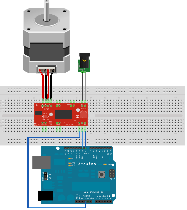
Example 1.5: Moving when a button is pressed
This example is almost exactly the same as Example 1, but we've
added a button. When the sketch is running, it waits for a button
press (a LOW on Arduino pin 3) and then it starts to rotate the
stepper motor for 3200 steps. It is written in such a way as to be
'non-blocking', which means you can easily add other things into the
loop() function without having to stop those things in order to run
the stepper motor. (Much like the way AccelStepper does it below.)
We added a push button switch between Pin 3 and ground, and then
used a 3.3K pull up resistor on pin 3 to 3.3V.
#define DISTANCE 3200
int StepCounter = 0;
int Stepping = false;
void setup()
{
pinMode(8, OUTPUT);
pinMode(9, OUTPUT);
digitalWrite(8, LOW);
digitalWrite(9, LOW);
pinMode(3,INPUT);
}
void loop() {
  if (digitalRead(3) == LOW && Stepping ==
      false)
{
Stepping = true;
}
if (Stepping == true)
{
digitalWrite(9, HIGH);
delay(1);
digitalWrite(9, LOW);
delay(1);
StepCounter = StepCounter + 1;
if (StepCounter == DISTANCE)
{
StepCounter = 0;
Stepping = false;
}
}
}
Example 1.6 : Using two buttons to move forward and reverse
This example is almost exactly like 1.5, except that we've added a
second button on Arduino Pin 2, again with a pull up resistor to
3.3V. When you press one button, the motor will move 3200 steps in
one direction, and when you press the other button, it will move
3200 steps in the other direction.
#define DISTANCE 3200
int StepCounter = 0;
int Stepping = false;
void setup() {
pinMode(8, OUTPUT);
pinMode(9, OUTPUT);
digitalWrite(8, LOW);
digitalWrite(9, LOW);
pinMode(2, INPUT);
pinMode(3, INPUT);
}
void loop() {
if (digitalRead(3) == LOW && Stepping ==
false)
{
digitalWrite(8, LOW);
Stepping = true;
}
  if (digitalRead(2) == LOW && Stepping ==
      false)
{
digitalWrite(8, HIGH);
Stepping = true;
}
if (Stepping == true)
{
digitalWrite(9, HIGH);
delay(1);
digitalWrite(9, LOW);
delay(1);
StepCounter = StepCounter + 1;
if (StepCounter == DISTANCE)
{
StepCounter = 0;
Stepping = false;
}
}
} Example 1.7: Moving when a switch is pressed at a very specific
speed
This example is exactly like 1.5 in setup, but allows you to
specify the exact RPM of the motor. It will spin the motor at that
speed as long as the button is held down.
/* This example assumes a step/direction driver with Step on pin
9, Direction on pin 8
* And an input switch on pin 3. The switch is a
switch to ground, with pin 3 pulled
* high with a pullup resistor. When the switch is
turned on (closed, i.e. goes low)
* the the sepper motor steps at the rate specified
(104 RPM in this code, with
* 1/8th microstepping of a 200 steps/rev motor)
*/
#define
RPMS
104.0
#define
STEP_PIN
9
#define
DIRECTION_PIN
8
#define
GO_PIN
3
#define
STEPS_PER_REV 200
#define MICROSTEPS_PER_STEP 8
#define MICROSECONDS_PER_MICROSTEP
(1000000/(STEPS_PER_REV * MICROSTEPS_PER_STEP)/(RPMS / 60))
uint32_t LastStepTime = 0;
uint32_t CurrentTime = 0;
void setup()
{
pinMode(STEP_PIN, OUTPUT);
pinMode(DIRECTION_PIN, OUTPUT);
digitalWrite(STEP_PIN, LOW);
digitalWrite(DIRECTION_PIN, LOW);
pinMode(GO_PIN,INPUT);
}
void loop() {
if (digitalRead(GO_PIN) == LOW)
{
CurrentTime = micros();
if ((CurrentTime - LastStepTime) >
MICROSECONDS_PER_MICROSTEP)
{
LastStepTime = CurrentTime;
digitalWrite(STEP_PIN,
HIGH);
delayMicroseconds((MICROSECONDS_PER_MICROSTEP * 0.9)/2);
digitalWrite(STEP_PIN, LOW);
delayMicroseconds((MICROSECONDS_PER_MICROSTEP * 0.9)/2);
}
}
}
Example 1.8: Fine speed control of two motors with a joystick
This example was written by R. A. Stephenson and he kindly allowed us to
use it. He has a two axis joystick on two analog inputs, and two EasyDrivers
controlling two stepper motors. The analog inputs are sampled, and a non-blocking
recorded time method is used to determine when the step pulses should happen.
His code is nicely commented and shows that useful, real life projects can
be made without complicated libraries, but instead just by keeping careful
track of time. If you'd like to reach out to him with any questions, his
email address is theropod@yahoo.com
/*

Written by R. A. Stephenson for prototype Pan/Tilt Alt/Az small telescope or
binocular set pointer application.

Significant advice, and editorial guidance, supplied by Brian Schmalz
(designer of the Easy Driver® bipolar stepper motor driver board).

Test equipment:
Arduino® Nano, 2 - Easy Driver® bipolar stepper motor driver boards,
analog 2 axis joystick and salvage bipolar stepper motors,
which are both 1.8 degree per full step, being driven at 1/8 microstepping (Easy Driver default),
which equates to 200 full steps multiplied by 8 = 1600 pulses for one complete revolution of the motor
left right gearing provided by windshield wiper worm and wheel gears (ratio TBD)
up and down gearing provided by paper shredder square cut reduction set (ratio TBD)
project origin; July, 2018, this edit, Version 5.1, began Jan. 2019

last modified: Jan. 23, 2019


*/
//define Arduino pin assignments
//
#define step_pinx 2 // Arduino Digital output pin #2 is step signal pin for X axis L/R
#define dir_pinx 3 // Arduino Digital output pin #3 is direction control pin for X axis L/R
#define x_pin A0 // Arduino analog input from joystick for X axis L/R
#define y_pin A1 // Arduino analog input from joystick for Y axis U/D
#define step_piny 5 // Arduino Digital output pin #5 is step speed select signal pin for Y axis U/D
#define dir_piny 4 // Arduino Digital output pin #4 is direction control pin for Y axis U/D
//
//declare global variable
//
int xaxisState = LOW; //state of x axis stepper pulse set to ON
int yaxisState = LOW; //state of y axis stepper pulse set to ON
//
int XStepDelay;
int YStepDelay;
//
//
const long xhigh = 180; //interval to pulse X axis at slowest speed, change to fit application
const long xlow = 1; //interval to pulse X axis at highest speed, change to fit application
//
const long yhigh = 180; //interval to pulse Y axis at slowest speed, change to fit application
const long ylow = 2; //interval to pulse Y axis at highest speed, change to fit application
//
//
unsigned long previousMillisX = 0; //
unsigned long previousMillisY = 0; //
//
//
//
void setup() {
  //
  delay(1000); //1 second delay to allow easy drivers to power up
  //
  pinMode(dir_pinx, OUTPUT);
  pinMode(step_pinx, OUTPUT);
  pinMode(dir_piny, OUTPUT);
  pinMode(step_piny, OUTPUT);
  digitalWrite(step_pinx, xaxisState) ; //used in state machine switching for the stepper logic final drive (on or off setting)
  digitalWrite(step_piny, yaxisState) ; //used in state machine switching for the stepper logic final drive (on or off setting)
  //
}
//
void loop() {
  //
  unsigned long currentMillisX = millis(); //
  unsigned long currentMillisY = millis(); //
  //
  //
  int xValue = analogRead(A0); // x axis variable for joystick inputs controlling r/l PIN DEPENDENT!
  int yValue = analogRead(A1); // y axis variable for joystick inputs controlling u/d PIN DEPENDENT!
  //
  //
  if (xValue > 520) {
    //if joystick moved RIGHT out of "null zone" to limit jitter
    digitalWrite(dir_pinx, HIGH); // motor direction signal sent to Easy Driver X axis DIR pin (ON)
    XStepDelay = map(xValue, 520, 1023, xhigh, xlow);
  }
  else if (xValue < 480) {
    //if joystick moved LEFT out of null zone to limit jitter
    digitalWrite(dir_pinx, LOW); // motor direction signal sent to Easy Driver X axis DIR pin (OFF)
    XStepDelay = map(xValue, 0, 480, xlow, xhigh);
  }
  else if (yValue > 520) {
    // if joystick moved DOWN out of null zone to limit jitter
    digitalWrite(dir_piny, HIGH); //motor direction signal to Y axis Easy Driver DIR pin (ON)
    YStepDelay = map(yValue, 530, 1023, yhigh, ylow); //
  }
  else if (yValue < 480) {
    //if joystick moved UP out of null zone to limit jitter
    digitalWrite(dir_piny, LOW); //motor direction signal to Y axis Easy Driver DIR pin (OFF)
    YStepDelay = map(yValue, 0, 480, ylow, yhigh); //
  } else {
    digitalWrite(dir_piny, LOW); //motor direction signal to Y axis Easy Driver DIR pin (OFF)
    digitalWrite(dir_pinx, LOW); // motor direction signal sent to Easy Driver X axis DIR pin (OFF)
    // Setting LOW saves a bit of power
    //could include signal to set Easy Driver(s) in "sleep" mode for geared drivetrains
  }
  //_____________
  // If X axis (L/R) (Azimuth) motor needs to take a step, give it a step for the correct length of time,
  //when that time has expired end the pulse signal
  if ((xValue >= 520 || xValue <= 480) && ((unsigned long)(currentMillisX - previousMillisX) >= XStepDelay)) {
    //if the joystick X axis values goes outside the null zone calculate
    //how long it's been against those joystick values and control step pulse length
    xaxisState = !xaxisState; // logic switch between states of step pulse pin on/off
    digitalWrite (step_pinx, xaxisState); //control signal for step pin
    //if the motor pulse is off, turn it on, and if the pulse is on, turn it off
    previousMillisX = currentMillisX; //save the last x channel/axis pulse time on or off
  }
  else if (xValue <= 520 || xValue >= 480){ //if the joystick input isn't out of the null zone
    digitalWrite(step_pinx, LOW); //turn off the step pulse
  }
  //________________
  // If Y axis (U/D) (Altitude) motor needs to take a step, give it a step over the correct length of time,
  //after that time has expired end the pulse signal
  if ((yValue >= 520 || yValue <= 480) && ((unsigned long)(currentMillisY - previousMillisY) >= YStepDelay)){
    //if the joystick Y axis values goes outside the null zone calculate
    //how long it's been against those joystick values and control step pulse length
    yaxisState = !yaxisState; // logic switch between states of step pulse pin on/off
    digitalWrite (step_piny, yaxisState); //control signal for step pin
    //if the motor pulse is off, turn it on, and if the pulse is on, turn it off
    previousMillisY = currentMillisY; //save the last y channel/axis pulse time
  }
  else if (yValue <= 520 || yValue >= 480){ //if the joystick input isn't out of the null zone
    digitalWrite(step_piny, LOW); //turn off the step pulse
    //
    //restart loop
  }
}
Example 2: Moving back and forth
If we take Example 1, and simply change the sketch a little bit, we
can move a certain number of steps forward or backward. Like so:
int Distance = 0; // Record the number of steps we've
taken
void setup()
{
pinMode(8, OUTPUT);
pinMode(9, OUTPUT);
digitalWrite(8, LOW);
digitalWrite(9, LOW);
}
void loop() {
digitalWrite(9, HIGH);
delayMicroseconds(100);
digitalWrite(9, LOW);
delayMicroseconds(100);
Distance = Distance + 1; // record this
step
// Check to see if we are at the end of our move
if (Distance == 3600)
{
// We are! Reverse direction (invert
DIR signal)
if (digitalRead(8) == LOW)
{
digitalWrite(8, HIGH);
}
else
{
digitalWrite(8, LOW);
}
// Reset our distance back to zero
since we're
// starting a new move
Distance = 0;
// Now pause for half a second
delay(500);
}
}
Now using this sketch, we move for 3600 steps in one direction,
pause for a bit, and move 3600 steps in the other direction. I'm
sure you can figure out how to make many different lengths of moves
now. And you can change the delay between steps for each move to
occur at separate speeds.
Note that, just like example 1, each 'step' from the code's
perspective is 1/8th of the motor's full step, because we are
assuming the use of the EasyDriver in 1/8th microstep mode. If you
use the Big Easy Driver, it's default is 1/16 microstep, so adjust
your expectations for motor motion accordingly.
Example 3: Using a pre-built library - AccelStepper
One thing the above examples can't do well is handle multiple
steppers from the same Arduino or chipKIT. Also, acceleration and
deceleration are difficult as well. Other people have run into this
problem, and so now we have libraries that we can download and
install into the Arduino IDE or MPIDE to fix these problems.
Download the zip file for the AccelStepper library from this
page. Unzip the downloaded file, and place the AccelStepper in
to the libraries folder in your Arduino install directory. Note that
for MPIDE (chipKIT) users, you need to copy the AccelStepper folder
into both the libraries folder at the top level as well as
\hardware\pic32\libraries so that both the AVR and PIC32 sides can
use it.
Using the same hardware from Example 1, restart the IDE, and enter
the following sketch:
#include <AccelStepper.h>
// Define a stepper and the pins it will use
AccelStepper stepper(AccelStepper::DRIVER, 9, 8);
int pos = 3600;
void setup()
{
stepper.setMaxSpeed(3000);
stepper.setAcceleration(1000);
}
void loop()
{
if (stepper.distanceToGo() == 0)
{
delay(500);
pos = -pos;
stepper.moveTo(pos);\
}
stepper.run();
}
This code does basically the same thing as Example 2, but
using acceleration/deceleration via the AccelStepper library, and
running for twice as many steps. (Thanks Mr. Duffy for pointing out
this important fact!) The reason it runs twice as many steps is
because we do "pos = -pos" to keep things short and simple. This
means that it will run from 0 to 3600, then from 3600 to -3600
(which is 7200 steps).
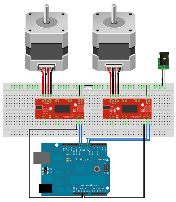
Example 4: Running multiple stepper motors
One of the great things about the AccelStepper library is that you
can run as many stepper motors as you want, at the same time, just
by making more AccelStepper objects. Now, if you try to run them too
fast, the steps won't be smooth, so you have to be careful not to
load down the Arduino too much. The chipKIT does not have this
problem because it is so much faster than the Arduino.
In this diagram, we now have two Easy Drivers and two stepper
motors. We just need 2 more pins from the Arduino to add this second
motor.
The code for this example is shown
below:
#include <AccelStepper.h>
// Define two steppers and the pins they will use
AccelStepper stepper1(AccelStepper::DRIVER, 9, 8);
AccelStepper stepper2(AccelStepper::DRIVER, 7, 6);
int pos1 = 3600;
int pos2 = 5678;
void setup()
{
stepper1.setMaxSpeed(3000);
stepper1.setAcceleration(1000);
stepper2.setMaxSpeed(2000);
stepper2.setAcceleration(800);
}
void loop()
{
if (stepper1.distanceToGo() == 0)
{
pos1 = -pos1;
stepper1.moveTo(pos1);
}
if (stepper2.distanceToGo() == 0)
{
pos2 = -pos2;
stepper2.moveTo(pos2);
}
stepper1.run();
stepper2.run();
}
You can see that for this example, I just copied and pasted the code
from Example 3 and made two positions and two steppers. This example
code is very simple and not all that useful, but you can study the
existing examples from the AccelStepper library, and read the help
pages on the different functions, and get good ideas about what else
you can do with your stepper control.
Example 5: Changing motor speed
Sometimes you need to have real time control of the speed of the
stepper motor. Say, for example, you're making a mount for your
telescope. You get a really nice geared stepper motor, you get a Big
Easy Driver with 16x microstepping, and you connect them all up. But
how do you control the speed of the stepper so that it matches the
speed of the stars across the sky?
One easy way is to use a potentiometer, which produces an analog
voltage output that you can control. The sketch code can read this
analog value using the analogRead() command. Then we can use that
value to change how fast we move the motor.
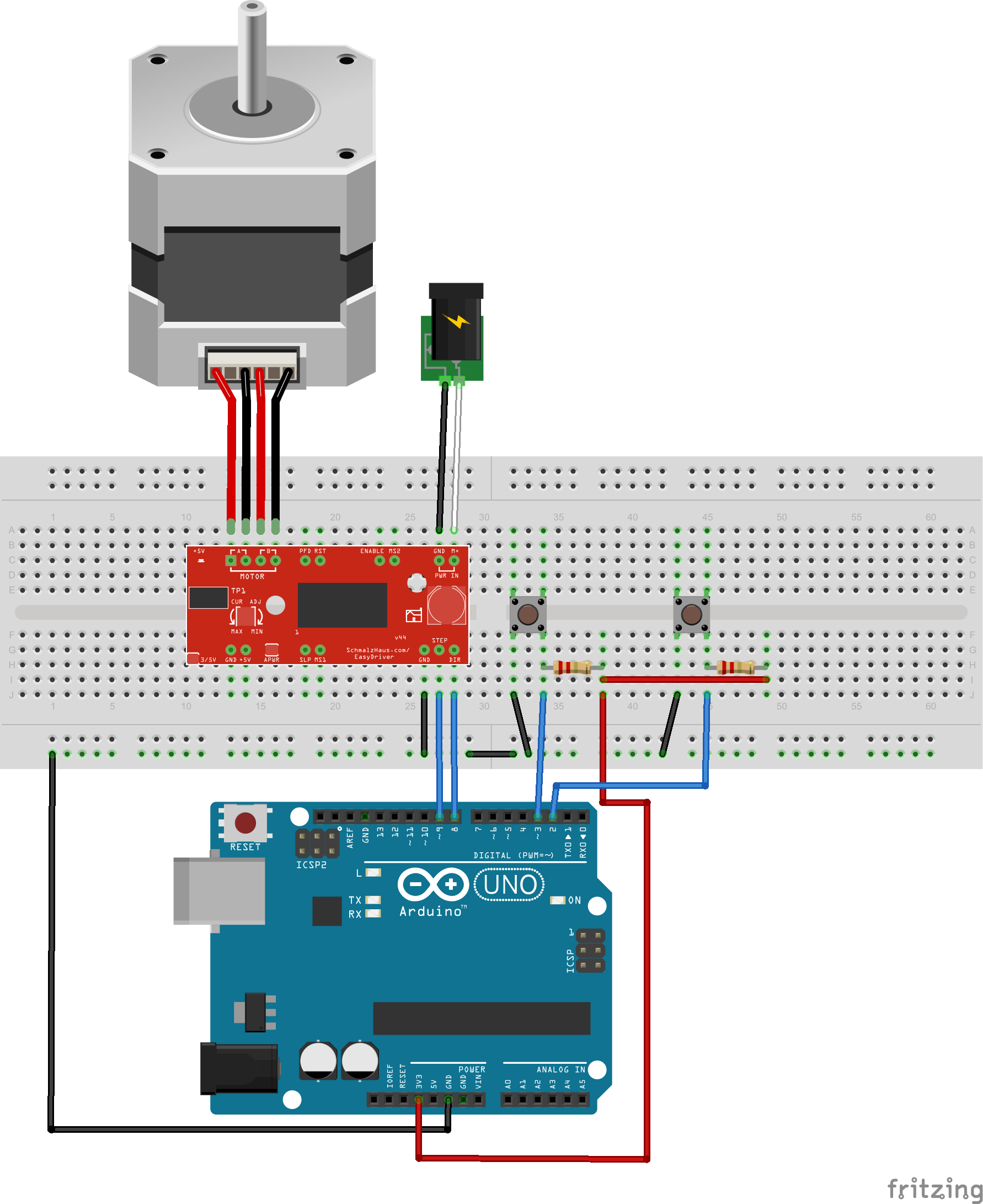
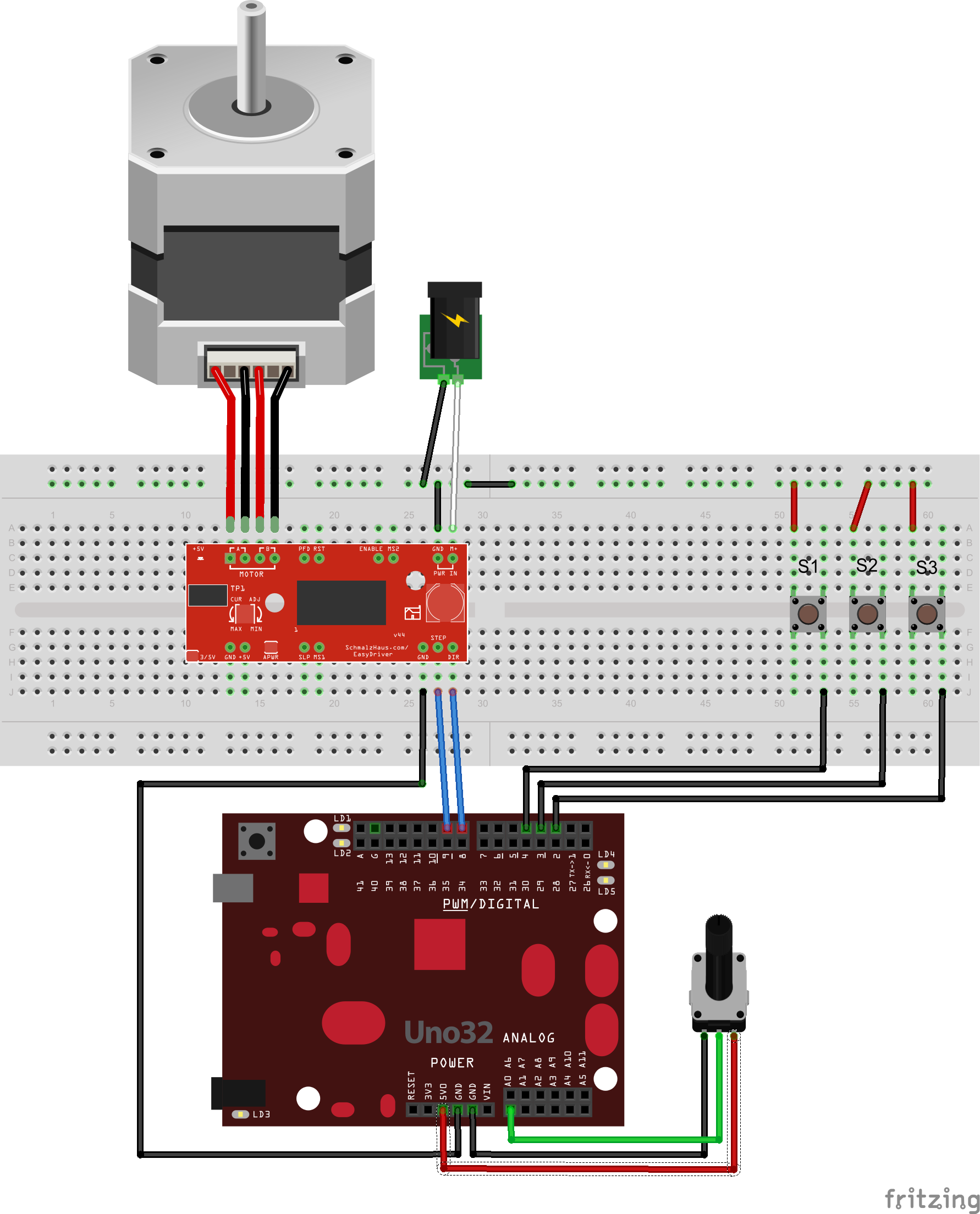
Here's a simple example of this concept. We've added a pot and three
push buttons to our single stepper motor circuit. Pushing switch S1
will cause the motor to turn in one direction, S3 will cause it to
turn in the other direction, and S2 will stop the motor. You can
then use the pot to adjust the exact speed of the motor while
stepping. You may want to adjust the MAX_SPEED and MIN_SPEED values
in the code for you application - depending on your particular
setup, you may want the pot's speed range to be different from what
we've written here.
Just to show how similar these circuits look, we've also included a
version of the diagram with a chipKIT Uno32 board. (Any Arduino or
chipKIT board will work for any of these examples, of course. The
Uno and Uno32 are just easy to diagram.)
The code for this example is shown
below:
// Example5 code for Brian
          Schmalz's Easy Driver Example page
//
          http://www.schmalzhaus.com/EasyDriver/EasyDriverExamples.html
#include <AccelStepper.h>
// Define the stepper and the pins it will use
AccelStepper stepper1(AccelStepper::DRIVER, 9, 8);
// Define our three input button pins
#define LEFT_PIN 4
#define STOP_PIN 3
#define RIGHT_PIN 2
// Define our analog pot input pin
#define SPEED_PIN 0
// Define our maximum and minimum speed in steps
          per second (scale pot to these)
#define MAX_SPEED 500
#define MIN_SPEED 0.1
void setup() {
  // The only AccelStepper value we have to
          set here is the max speeed, which is higher than we'll ever go
stepper1.setMaxSpeed(10000.0);
  // Set up the three button inputs, with
          pullups
pinMode(LEFT_PIN, INPUT_PULLUP);
pinMode(STOP_PIN, INPUT_PULLUP);
pinMode(RIGHT_PIN, INPUT_PULLUP);
}
void loop() {
  static float current_speed =
          0.0;         // Holds
          current motor speed in steps/second
  static int analog_read_counter =
          1000;    // Counts down to 0 to fire analog
          read
  static char sign =
          0;


          // Holds -1, 1 or 0 to turn the motor on/off and control
          direction
  static int analog_value =
          0;


          // Holds raw analog value.
  // If a switch is pushed down (low), set the
          sign value appropriately
if (digitalRead(LEFT_PIN) == 0) {
sign = 1;
}
  else if (digitalRead(RIGHT_PIN) == 0)
          {
sign = -1;
}
else if (digitalRead(STOP_PIN) == 0) {
sign = 0;
}
  // We only want to read the pot every so
          often (because it takes a long time we don't
  // want to do it every time through the main
          loop).
if (analog_read_counter > 0) {
analog_read_counter--;
}
else {
analog_read_counter = 3000;
    // Now read the pot (from 0 to
          1023)
    analog_value =
          analogRead(SPEED_PIN);
    // Give the stepper a chance to
          step if it needs to
stepper1.runSpeed();
    //  And scale the pot's
          value from min to max speeds
    current_speed = sign *
          (((analog_value/1023.0) * (MAX_SPEED - MIN_SPEED)) +
          MIN_SPEED);
    // Update the stepper to run at
          this new speed
stepper1.setSpeed(current_speed);
}
  // This will run the stepper at a constant
          speed
stepper1.runSpeed();
}
Some explanation on this example code: Because reading the analog
value takes a (relatively) long period of time, and during that time
we can't be updating the stepper motor's position (that only happens
in the runSpeed() call) we only grab a new analog value every 3000
times through the main loop. We do this by using a counter called
analog_read_counter, and decrementing it each time through the loop
until it gets to zero. Then we reload it with 3000, and perform the
analog conversion.
We've also inserted a runSpeed() call between the analog conversion
and the math necessary to scale the result to MAX_SPEED and
MIN_SPEED. This is because that math also takes a (relatively) long
time, and so we want to give the stepper a chance to step (if it
needs to) in between these to time intensive operations.
You can adjust the values of MIN_SPEED and MAX_SPEED to make the
range of speeds whatever you want. Note that there are only 1024
possible values that the analogRead() call can return, and so there
are only that many discrete speeds the motor can take on.
For this example (because we wanted it to be just a fixed speed) we
did not use the normal AccelStepper run() call, but rather the
runSpeed() call.
Example 6: Changing motor speed -
With an Adafruit Motor Shield (v1)
This example does exactly the same thing as Example 5, but instead
of using an Easy Driver or Big Easy Driver it uses an Adafruit Motor
Shield. This first sketch is for the v1.2 shield, and the next
sketch (see below) is for the v2 shield.
Also note that because the v1 AFMotorShield uses up almost all of
the digital I/O pins, we had to move the three buttons over to the
analog inputs. This is fine because you can always use analog input
pins as digital inputs as well. We are also not using any
microstepping in this example, so our motor has 200 steps/rev.
And of course, Fritzing doesn't have the Adafruit Motor Shield, so I
can't easily create a drawing for you. But it's very simple - the
stepper motor goes into the M1 and M2 terminals on the Motor Shield,
you put your motor power into the M+ and GND terminals on the motor
shield, take the three switch wires and connect them to A5, A4 and
A3, the center tap of the pot goes to A0, and then just tie the
other side of all of the switches to GND and the top and bottom of
the pot to +5 and GND, and you're all set. I tested this code with
an Arduino Uno. (I tried with an UNO32 but I couldn't get the analog
inputs to use built-in pullups because I don't think the UNO32 can
do that.)
// Example6 code for Brian Schmalz's Easy Driver Example page
//
      http://www.schmalzhaus.com/EasyDriver/EasyDriverExamples.html
#include <AccelStepper.h>
#include <AFMotor.h>
// Define the stepper and the pins it will use
AF_Stepper motor1(200, 1);
// you can change these to DOUBLE or INTERLEAVE or
MICROSTEP!
void forwardstep() {
motor1.onestep(FORWARD, SINGLE);
}
void backwardstep() {
motor1.onestep(BACKWARD, SINGLE);
}
AccelStepper stepper1(forwardstep, backwardstep); // use
functions to step
// Define our three input button pins
#define LEFT_PIN A5
#define STOP_PIN A4
#define RIGHT_PIN A3
// Define our analog pot input pin
#define SPEED_PIN A0
// Define our maximum and minimum speed in steps per second
(scale pot to these)
#define MAX_SPEED 500
#define MIN_SPEED 0.1
void setup() {
// The only AccelStepper value we have to set here
is the max speeed, which is higher than we'll ever go
stepper1.setMaxSpeed(500.0);
// Set up the three button inputs, with pullups
pinMode(LEFT_PIN, INPUT_PULLUP);
pinMode(STOP_PIN, INPUT_PULLUP);
pinMode(RIGHT_PIN, INPUT_PULLUP);
}
void loop() {
static float current_speed =
0.0; // Holds
current motor speed in steps/second
static int analog_read_counter =
1000; // Counts down to 0 to fire analog read
static char sign =
0;
// Holds -1, 1 or 0 to turn the motor on/off and control direction
static int analog_value =
0;
// Holds raw analog value.
// If a switch is pushed down (low), set the sign
value appropriately
if (digitalRead(LEFT_PIN) == 0) {
sign = 1;
}
if (digitalRead(RIGHT_PIN) == 0) {
sign = -1;
}
if (digitalRead(STOP_PIN) == 0) {
sign = 0;
}
// We only want to read the pot every so often
(because it takes a long time we don't
// want to do it every time through the main
loop).
if (analog_read_counter > 0) {
analog_read_counter--;
}
else {
analog_read_counter = 3000;
// Now read the pot (from 0 to 1023)
analog_value = analogRead(SPEED_PIN);
// Give the stepper a chance to step if
it needs to
stepper1.runSpeed();
// And scale the pot's value from
min to max speeds
current_speed = sign *
((analog_value/1023.0) * (MAX_SPEED - MIN_SPEED)) + MIN_SPEED;
// Update the stepper to run at this new
speed
stepper1.setSpeed(current_speed);
}
// This will run the stepper at a constant speed
stepper1.runSpeed();
}
And with an Adafruit Motor Shield V2
Note that the Left, Stop and Right inputs are now back on digital
pins 2, 3 and 4 for the V2 shield, as it doesn't need them and so
we can use them again.
// Example6 code for Brian Schmalz's Easy Driver Example page
//
http://www.schmalzhaus.com/EasyDriver/EasyDriverExamples.html
#include <AccelStepper.h>
#include <Wire.h>
#include <Adafruit_MotorShield.h>
// Define the stepper and the pins it will use
Adafruit_MotorShield AFMS = Adafruit_MotorShield();
Adafruit_StepperMotor *motor1 = AFMS.getStepper(200,
      1);
// you can change these to DOUBLE or INTERLEAVE or
      MICROSTEP!
void forwardstep() {
motor1->onestep(FORWARD, SINGLE);
}
void backwardstep() {
motor1->onestep(BACKWARD, SINGLE);
}
AccelStepper stepper1(forwardstep, backwardstep); //
      use functions to step
// Define our three input button pins
#define LEFT_PIN 2
#define STOP_PIN 3
#define RIGHT_PIN 4
// Define our analog pot input pin
#define SPEED_PIN A0
// Define our maximum and minimum speed in steps per
      second (scale pot to these)
#define MAX_SPEED 500
#define MIN_SPEED 0.1
void setup() {
AFMS.begin();
  // The only AccelStepper value we have to set
      here is the max speed, which is higher than we'll ever go
stepper1.setMaxSpeed(500.0);
// Set up the three button inputs, with pullups
pinMode(LEFT_PIN, INPUT_PULLUP);
pinMode(STOP_PIN, INPUT_PULLUP);
pinMode(RIGHT_PIN, INPUT_PULLUP);
}
void loop() {
  static float current_speed =
      0.0;         // Holds
      current motor speed in steps/second
  static int analog_read_counter =
      1000;    // Counts down to 0 to fire analog read
  static char sign =
      0;


      // Holds -1, 1 or 0 to turn the motor on/off and control direction
  static int analog_value =
      0;


      // Holds raw analog value.
  // If a switch is pushed down (low), set the
      sign value appropriately
if (digitalRead(LEFT_PIN) == 0) {
sign = 1;
}
  if (digitalRead(RIGHT_PIN) == 0)
      {
sign = -1;
}
if (digitalRead(STOP_PIN) == 0) {
sign = 0;
}
  // We only want to read the pot every so often
      (because it takes a long time we don't
  // want to do it every time through the main
      loop).
if (analog_read_counter > 0) {
analog_read_counter--;
}
else {
analog_read_counter = 3000;
// Now read the pot (from 0 to 1023)
    analog_value =
      analogRead(SPEED_PIN);
    // Give the stepper a chance to step
      if it needs to
stepper1.runSpeed();
    //  And scale the pot's value
      from min to max speeds
    current_speed = sign *
      ((analog_value/1023.0) * (MAX_SPEED - MIN_SPEED)) + MIN_SPEED;
    // Update the stepper to run at this
      new speed
stepper1.setSpeed(current_speed);
}
// This will run the stepper at a constant speed
stepper1.runSpeed();
}
Example 7: Serial command input
Using the exact same hardware setup as Example 1, this sketch
illustrates how to use simple one letter commands from the serial
port to control the direction and speed of the stepper motor.
// Example7 for Brian Schmalz's Easy Driver Example page
//
http://www.schmalzhaus.com/EasyDriver/EasyDriverExamples.html
// We control the direction and speed of a stepper using
the
// arduino serial port. Note that (if using the Serial
Monitor)
// you will need to press Enter after each command.
#include <AccelStepper.h>
AccelStepper stepper(AccelStepper::DRIVER, 9, 8);
int spd = 1000; // The current speed in
steps/second
int sign = 1; // Either 1, 0
or -1
void setup()
{
Serial.begin(9600);
stepper.setMaxSpeed(1000);
stepper.setSpeed(1000);
}
void loop()
{
char c;
if(Serial.available()) {
c = Serial.read();
if (c == 'f') { // forward
sign = 1;
}
if (c == 'r') { // reverse
sign = -1;
}
if (c == 's') { // stop
sign = 0;
}
if (c == '1') { // super slow
spd = 10;
}
if (c == '2') { // medium
spd = 100;
}
if (c == '3') { // fast
spd = 1000;
}
stepper.setSpeed(sign * spd);
}
stepper.runSpeed();
}
Using stepper motors with RC servo inputs
This
page describes a one channel system (running on a chipKIT
Fubarino Mini, with a Big Easy Driver) that reads RC servo channel
information from a receiver and spins a stepper motor accordingly.
This
page describes a two channel version.
References:
Easy Driver Pinout:
Questions? E-mail me at