 Big Easy Driver Stepper Motor
Driver
Big Easy Driver Stepper Motor
Driver
An Open Source Hardware
Stepper Motor Driver
|
|
|
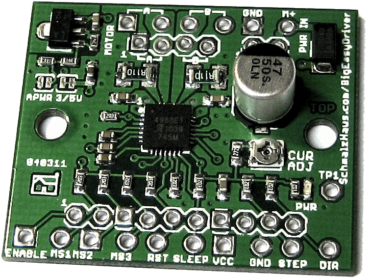
BigEasyDriver
v1.1
|
Big
Easy Driver v1.2
|
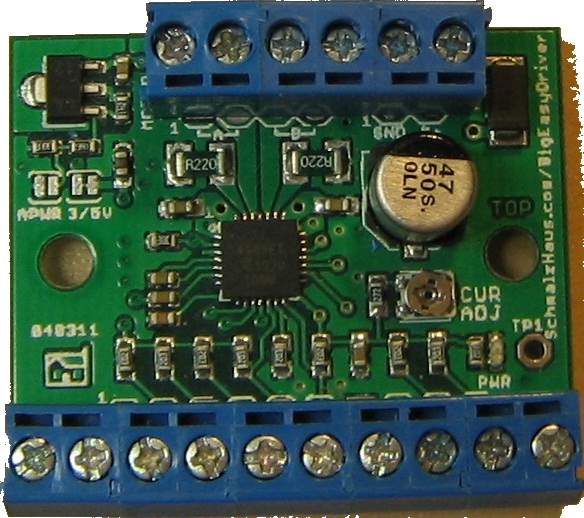
BED
v1.1 with screw terminals on the top side
|
Description:
The Big Easy Driver is a stepper motor driver board for bi-polar
stepper motors up to 2A/phase. It is based on the Allegro A4983 or
A4988 stepper driver chip. It is the next version of the Easy Driver
board.
User Manual:
Download the latest version of the Big Easy Driver user manual here.
Quick Specs:
Each BigEasyDriver (BED) can drive up to about 2A per phase of a
bi-polar stepper motor. It defaults to 16
step microstepping mode. (So if your motor is 200 full steps per
revolution, you would get 3200 steps/rev using the Big Easy Driver.)
It is a chopper microstepping driver based on the Allegro
A4988 driver chip. For the complete specs of the design, read
the A4988 datasheet. It has a variable max current from about
0mA/phase to 2A/phase, although I have tested it to 2.2A/phase with
a heatsink and/or fan. It can take a maximum motor drive voltage of
around 35V, and includes on-board 5V/3.3V regulation, so only one
supply is necessary.
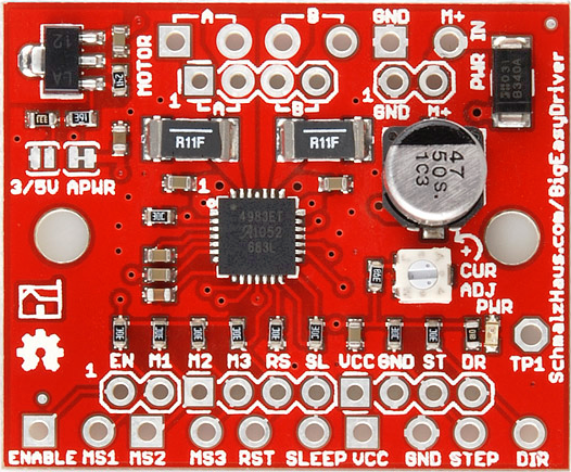
Quick Pin Description:
Please see the Allego A4988 data sheet linked above for complete
technical details. The Big Easy Driver is basically just a breakout
board for this driver chip, so the datasheet is your best source of
information about how it all works. However, if all you need is a
reference to the pins, here you go:
- GND : There are three GND (Ground) pins on the Big Easy
Driver. They are all connected together inside the board.
Connect the negative side of your power supply, as well as from
any other boards you are using to drive the Easy Driver to one
or more of the GND pins.
- M+ : This is the power input to the Easy Driver. Connect this
to the positive power supply lead. This should be a 6V to 30V,
3A (or more) power supply that is clean (low ripple).
- A and B : (four pins) These are the motor connections. See
below diagrams for how to hook these up. A and B are the two
coils of the motor, and can swap the two wires for a given coil
(it will just reverse the direction of the motor). Make CERTAIN
that this connection to the motor is solid, and NOT through a
connector that has any chance of intermittent contact (which
will fry the motor driver chip).
- STEP : This needs to be a 0V to 5V (or 0V to 3.3V if you've
set your Big Easy Driver that way) digital signal. Each rising
edge of this signal will cause one step (or microstep) to be
taken.
- DIR (Direction) : This needs to be a 0V to 5V (or 0V to 3.3V
if you've set your Big Easy Driver up that way) digital signal.
The level if this signal (high/low) is sampled on each rising
edge of STEP to determine which direction to take the step (or
microstep).
That's it - those are the only signals that you absolutely need
to connect to anything. All the rest below are optional - in other
words, the Big Easy Driver sets them to reasonable default values.
- MS1/MS2/MS3 : These digital inputs control the microstepping
mode. Possible settings are (MS1/MS2/MS3) : full step (0,0,0), half
step (1,0,0), 1/4 step (0,1,0), 1/8 step (1,1,0), and 1/16 step (1,1,1 : default).
- RST (reset) : This normally high input signal will reset the
internal translator and disable all output drivers when pulled
low.
- SLEEP : This normally high input signal will minimize power
consumption by disabling internal circuitry and the output
drivers when pulled low.
- EN (enable) : This normally low input signal will disable all
outputs when pulled high.
- VCC : This is an OUTPUT pin that will provide either 5V
(default) or 3.3V from the voltage regulator, at a small amount
of current (say 50mA - depends on input voltage) to power a
circuit that you may need powered.
Where to buy Big Easy Drivers:
I do not sell Big Easy Driver boards. This design is being released
into the general public just like the Easy Driver design. Anybody
can take the design presented on this page and do anything they want
with it. I'm providing Eagle schematic and board layouts as well as
a Bill Of Materials and instructions on how to build and use the
design. If you do decide to manufacture the Big Easy Driver for
yourself or for sale, please remember that royalties are the only
way that I can continue to provide support to Easy Driver users, so
contact me.
Status:
(11/04/12) Added a link in FAQ section below to (Big) Easy
Driver Example page - how to use your Big Easy Driver with an
Arduino or chipKIT board!
(11/04/12) Added note about how to calculate motor current from TP1
voltage (see below)
(8/19/11) Big EasyDriver v1.2 is now for sale at SparkFun
for $22.95
(6/19/11) Files published on this webpage - schematic, board layout,
BOM, etc.
(5/26/11) Big EasyDriver v1.2 has been accepted for production by
SparkFun
(5/17/11) Initial webpage created. More content to be filled in
after Maker Faire.
EasyDriver Hardware Versions
Matrix (guides and pictures be updated yet)
|
|
Schematic
|
Board
|
Picture
|
Guide
|
Eagle Files and BOM
|
BigEasyDriver v1.0
|
here
|
here
|
here
|
N.A.
|
here
|
BigEasyDriver
v1.1
|
here |
here
|
here
|
N.A. |
here
|
BigEasyDriver
v1.2
|
here |
here
|
here
|
N.A. |
here
|
Version Notes:
- BigEasyDriver V1.0 - Initial version. Tried to keep similar
board footprint to EasyDriver - not cool. Routing didn't work
well, heat dissipation didn't work well. Forgot pull-up
resistors on digital inputs.
- BigEasyDriver V1.1 - New form factor, got all of the EE stuff
right. Great power dissipation, works very well.
- BigEasyDriver V1.2 - Minor changes - silk screen cleanup,
sense resistors now 0.11 ohms, minor layout tweaks, and R13 is
now 2.49K. First SparkFun production version.
FAQ:
Q1) Do I
need a heatsink on that little chip?
A)
Probably not. Most of the time, you will be able to
get perfectly acceptable performance without running all the way up
to 2A/phase. Even without a heatsink, you will be able to get close
to 2A/phase. If, however, your BEDs will be enclosed, or in high
ambient temps, or you really want to push them (I've gotten to
2.2A/phase with heatsink and fan) then I recommend this little guy:
A FISCHER
ELEKTRONIK
34M6428. The board is designed for maximum heat dissipation,
so its really good at getting rid of the heat even without the
heatsink.
Q2) The
datasheet for the driver chip shows that the motor connects to pins
OUT1A, OUT1B, OUT2A and OUT2B, and the diagram in the datasheet has
one coil connected across OUT1A and OUT1B, and the other across
OUT2A and OUT2B. But the Big Easy Driver only has A, A, B, B
for motor connections, and it looks like one coil should be
connected across the two A pins and the other across the two B pins.
What's up with that?
A) Yeah. Ooops.
Clearly that was a pretty bad choice for the Big Easy Driver labels.
On a bi-polar stepper motor, there are four wires that connect to
two coils. Each coils has two wires. The Big Easy Driver calls those
two coils A and B. So one coils' wires are to be connected across
the two A pins, and the other coils' wires are to be connected
across the B pins. The driver chip datasheet refers to these two
coils as coil 1 and coil 2. Sorry for the confusion. See the diagram
below for the accurate connection diagram for the Big Easy Driver.
Q3) So if I
can't trust the silk screen, how do I know which way to turn the CUR
ADJ pot to set the current in my stepper motor to some value?
A) Well, there are two
methods. One is to run your motor at a nice constant speed, say 500
steps/s, and slowly and carefully turn the current adjustment pot
one way or the other (careful not to go past the mechanical end
stops if the pot you have has them) and listen, feel, and watch the
motor. There will normally be a place in the pot's range that
produces smooth microstep action and minimizes the 'buzz' of the
motor as it moves. That's probably a good place to leave it.
A) The other way to do it is
by measuring the voltage on TP1. Get your volt meter out, and put
the positive on TP1 and the negative on GND (any GND on the BED will
do), and set it to DC volts, low range (you'll be measuring between
0V and about 3.8V). You can turn the power off to the BED,
disconnect the motor from the BED, then turn power back on to the
BED to do this measurement. As you turn the pot, you will get
different voltages on TP1. You use the following equation to compute
what the motor current will be based on the voltage at TP1:
Itripmax = Vref/(8 * Rs)
Where Itripmax is the current that the driver will allow through to
the motor coil, Vref is the TP1 voltage, and Rs is the value of the
current sense resistor, which is .11 Ohms for the current BED.
So if you have 0.0V at for Vref, then the max current will be
(theoretically) 0A.
And if you have Vref maxed out at 3.8V, then the (theoretical)
current will be 4.3A.
Now, you clearly can't get 4.3A/phase out of the BED. So the maximum
usable range will probably be in the 0V to 1.76V (results in
2A/phase). Depending on if you have a heatsink, fan, low impedance
motor, etc.
One really big factor to success here is that the input voltage to
the BED must be high enough that the BED can actually limit the
current to the coils. If your motor coil resistance is too high, or
the input voltage is too low, then you won't get accurate
microstepping. In fact, you may not get any current chopping at all,
which means you're limited to half-step mode. (Since there will be
no microsteps.)
Q4) Do you have any examples of how to use
the Big Easy Driver with an Arduino or chipKIT board?
A) Yes! Check out this page
- everything there for the Easy Driver applies to the Big Easy
Driver.
Q5) Does it matter which order I power
things on? Can the Big Easy Driver be damaged by the order that
things power up?
A) As far as I know, no. If you have a microcontroller board
(like a chipKIT or Arduino) connected to your Big Easy Driver, and
the microcontroller is powered from a different power supply than
the BED is (say over USB from a PC), it might seem to make sense
that powering up the microcontroller first would apply voltages to
the Big Easy Driver pins before the BED is ready for them (since it
isn't powered up yet) and cause damage. Based on my understanding of
the input protection circuitry on the BED, and my extensive testing,
there should be no damage caused in this situation. This answer only
applies to the order in which power is applied to the boards - you
still must not disconnect a motor from a BED that has power.
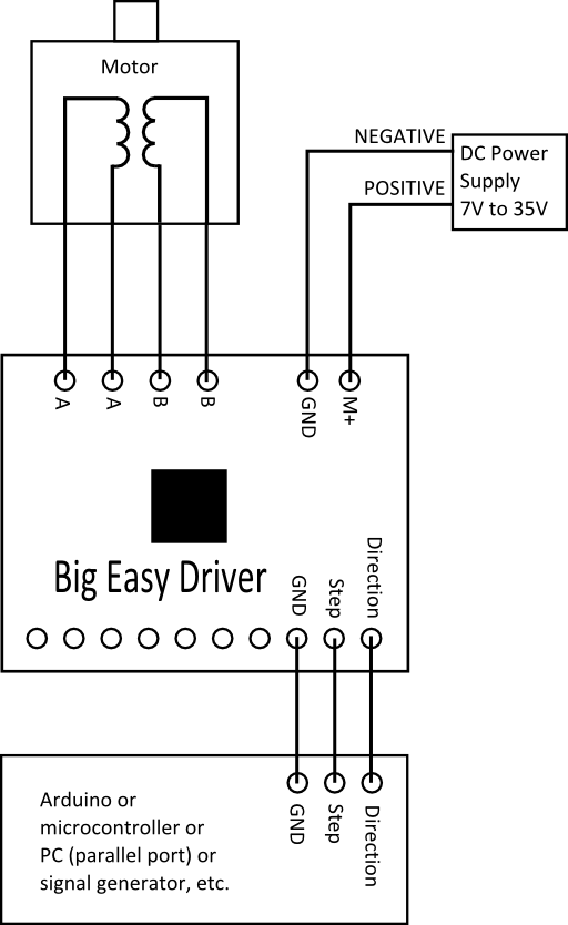
Motor Hookup
Here's a drawing on one way
to hook up a six wire stepper motor to the EasyDriver.
And here's how to hook up a
Big Easy Driver to a four wire stepper motor:
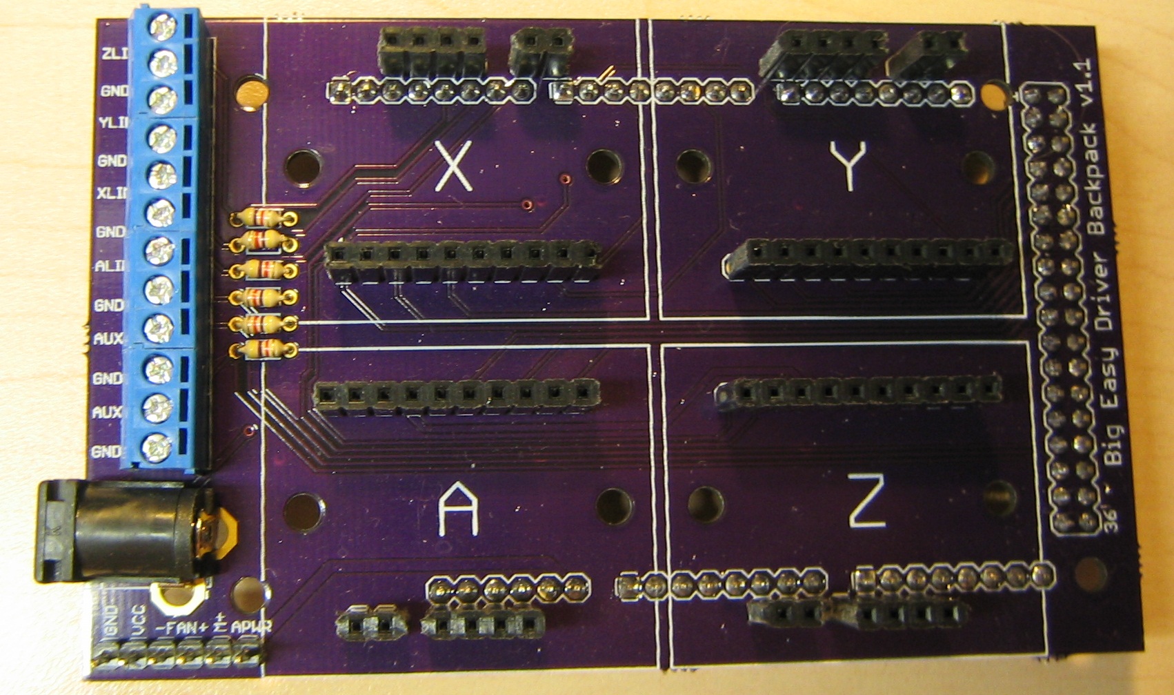
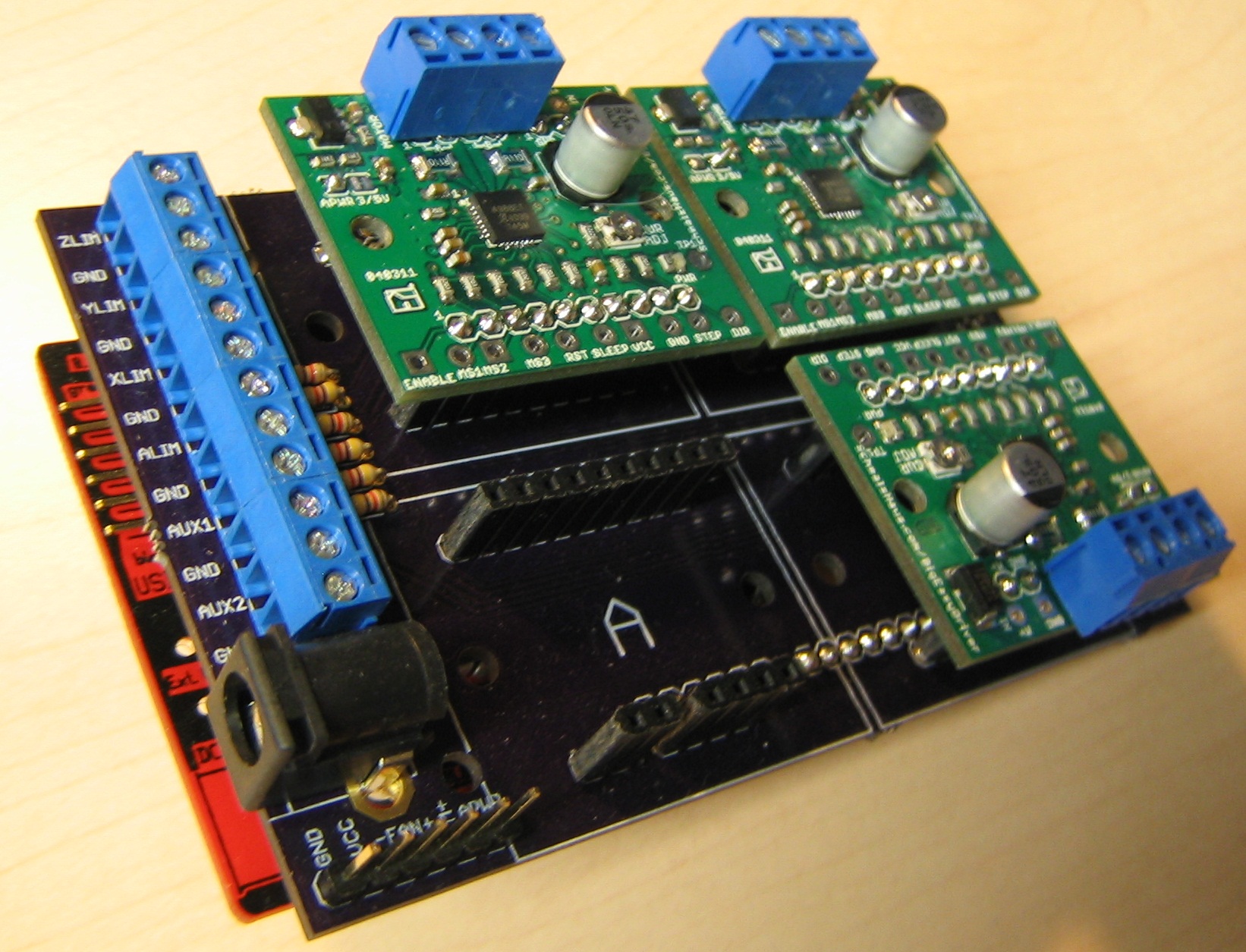
Big Easy Driver Backpack-
For Maker Faire San Mateo 2011 I threw together a quick Arduino
shield that could hold four Big Easy Drivers - I called it the Big
Easy Driver Backpack. This ran for 2 days straight, running my
little Fireball mill. I ran GRBL
on the Divolino
Arduino board and streamed G-code to it from a custom written
Libery Basic application.
Here are the Gerbers and Eagle files (schematic and board layout)
for the BED Backpack v1.1 (It's a
very simple board - just connectors really)
Questions? E-mail me at


